

I am an impatient person and, as such, I can’t wait for the time it takes the (factory bundled) hotbed of my printer to reach PETG temperatures. A 300x300mm bed, on a cold day, will take a considerable amount of time to get to 70C. So, I upgraded the bed to a 220v one (mains voltage where I live).
The french (local for me) representative for Tenlog StudioLab 39 offers this as a service, you can buy the printer with the new bed installed or a kit. If you do not feel comfortable putting your fingers near mains voltage, I strongly advise you to find your local reseller and ask for this to be done by an expert. Furthermore, this is an account on how I did it and, by no means, an advise to do it yourself.
I acquired the parts through aliexpress (most of those were available from local resellers but they offered the same items at an extra cost), I based my purchase list on what the official reseller offered and some other sources on this modification, here is the full BOM (some of these items I already had):
-
The heating pad:

-
The relay (beware, this part might be counterfeit, prefer locally sourced ones from reputable stores, it is not important at this loads for me but your mileage might vary):

-
A heat fuse:

-
A decent plug to be able to disconnect our bed easily:

-
A way to put a fuse between mains and the heating element:

- I also needed fuses, but I had those in stock for the printer, I matched the same fuse as used by the printer’s PSU:

-
If your model does not have a connector for the bed (cable goes straight into case), you will need one of these too:

-
Crimpers and terminals for the mains and other power terminals:

-
Crimper for DuPont/JST connectors:

-
Heat Shrink Tubing Insulation, moving parts and mains voltage require extra shielding:

-
A strong soldering iron:
- At least

-
But better:

- At least


I also got a lot of good ideas and safety instructions from TeachingTech youtube channel:
Also StudioLab 39 STL Download Section provides some useful info. The STLs available are outdated and most likely the only one that will fit your machine (if you have one of the new models) is the relay box.
First of all, I looked for a large surface to work. I commandeered the dining room table of my house.
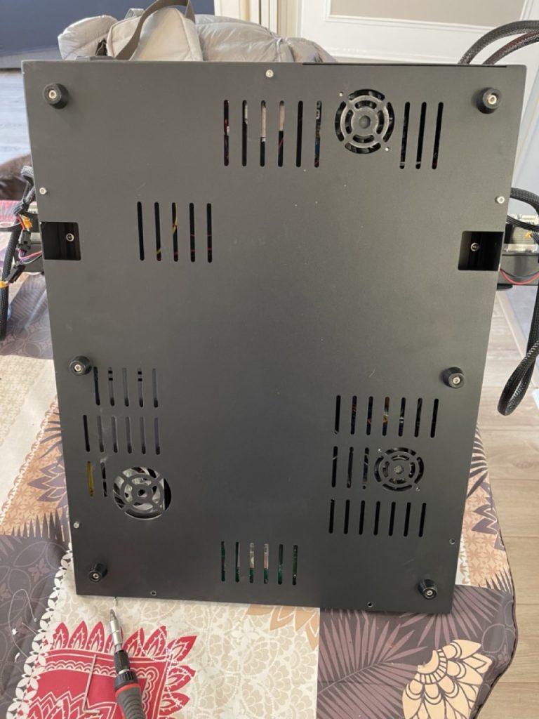
Remove the cover, there are quite a lot of screws. I used this chance to also upgrade the fans to Sunon Maglevs, and replace the PSU (I was using a spare one because mine needed some caps replaced, factory ones are underspec and eventually give up).

Most of your attention needs to be fixed on the upper board. I think the drivers in there are the extruder ones, it also contains the bed heater circuitry.
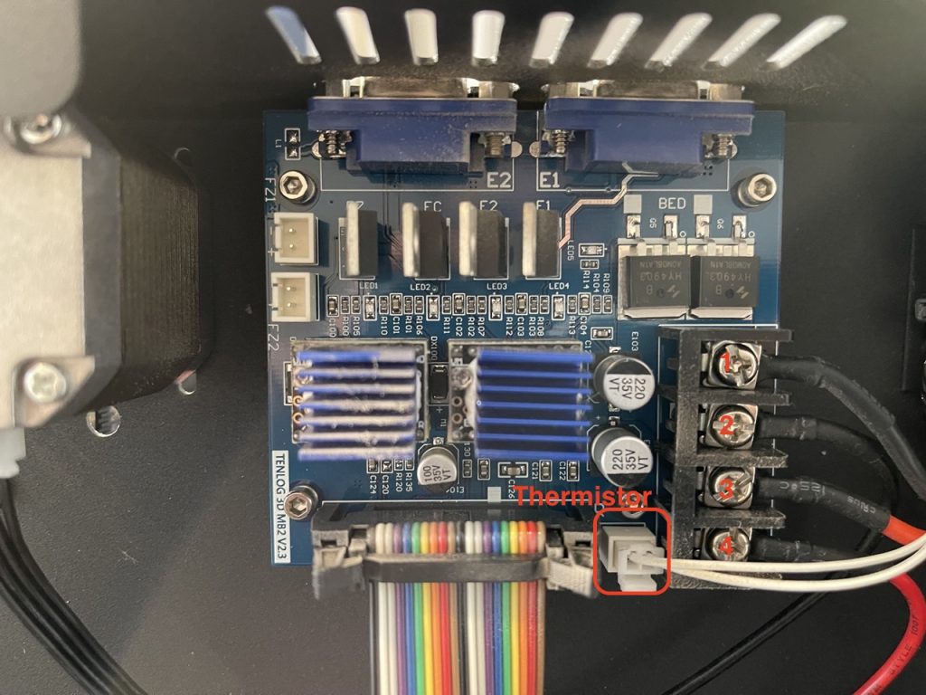
- 1 and 3 terminals go to the bed.
- 2 and 4 come from the PSU.
A Note: Do not fasten the Relay box until you have finished the wiring, you will need to access the underside of it (for the ground connection)
First connection I did was cables 1 and 3 to the relay’s 4 and 3 respectively.
At this point I started to crimp some terminals to do things properly.
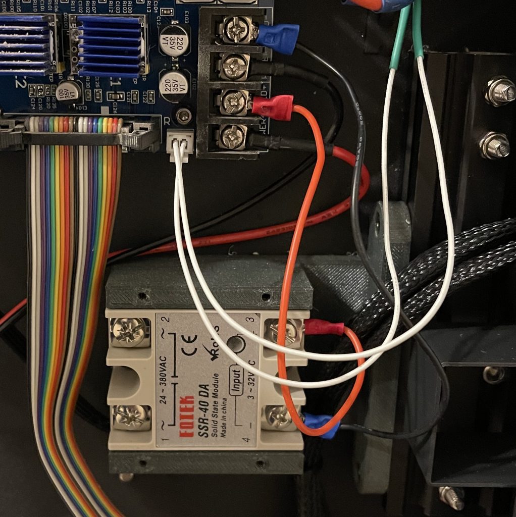
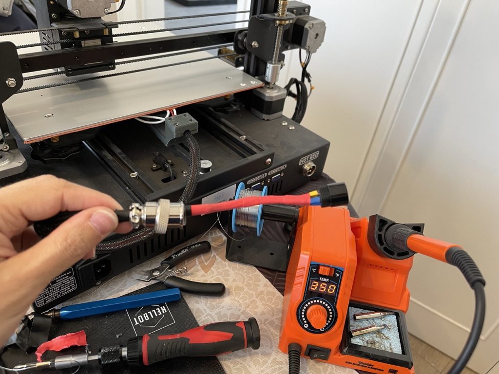
For the next part I decided to wire the GX20 plug to be able to later remove the bed.
I used left side for thermistor (polarity is not important) and right side for power (also polarity is not important but I kept it consistent within the case). This is the dangerous part, I added a sticky note with the wiring just to be sure not to cross the cables, you don’t want 220v going to your thermistor.
Next is wiring the relay to the PSU.
I connected the terminal 1 to the PSU Live/phase wire (P) , I interrupted this cable with a fuse holder and placed in it a fuse of the same value the printer uses for the PSU.
I connected the center screw of the relay (which is holding the relay to the box) to the ground (⏚) of the PSU. Terminal 2 of the relay to the red cable on the GX20 connector (polarity is not important but facilitates circuit interpretation when working on it).
Black cable of the GX20 connector goes directly to the Neutral on the PSU input (N).
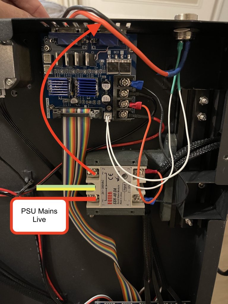
At this point I fastened the relay to the holding box, the box to the X profile (using T-Nuts) and the cover of the relay box to the box (this is VERY important, as those terminals are connected to mains voltage). I then closed the case and turned the machine.
Having the GX20 plug allows me to manage wiring outside without worrying about inside the case.
At this point the bed needs to come off, refer to the video by TeachingTech from above if you want to see this process, my hands were sort of full.
I had to de-solder the previous wiring, this was not an easy feat since the bed is a heat dissipator. I used the largest tip I had, the iron very hot and added some solder to ease the process.
The replacement then is just a sticker that goes under the existing bed.
I replaced the bed and assembled the GX20 male with the existing wires.
I reused the cable mesh provided with the original but added significant amounts of Shrink Wrap to isolate.
I tried to use the supplied part for managing the cable (pictured above as a gray piece clipping cables behind the bed) but it did not fit my model. It was loose and also impeded bed movement to the origin of Y. My guess is that supplied pieces work better with older models or with the modification to linear rails of the bed which raises it a bit.
To finish wiring I soldered the thermal fuse in the cable and adhered to the underside of it with polyimide tape.
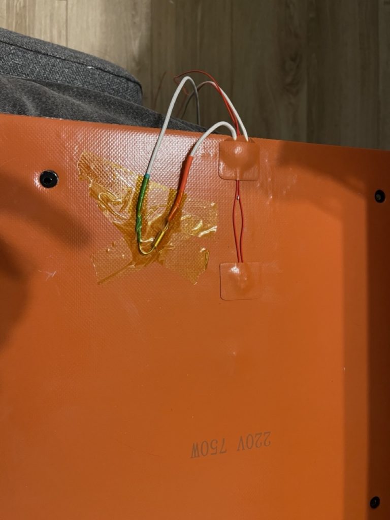
It is important that none of this is exposed as it is wired to phase. This fuse will cut power if temperature exceeds its rating (I got one for 110C if I recall correctly, I do not print anything that warrants a hotter bed).
After completing this, I just tidied up cables (used some shrink wrap because I did not have zip ties to replace the ones I cut and it also works better to keep wire mesh at bay).
Software side the only thing I had to do was run a PID Auto-tune which did not work because Tenlog uses an ancient version of marlin which is heavily customized.
End result, it works, there is a significant overshot when heating but some correction on the slicer compensates for it (I end up with about +5C of what I asked for most o the time)